An interesting article on how to machine a strut and rudder assembly for your boat...
Tales of mystery and… or how to spend lots of your free time!
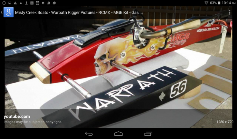
Last year I bought the hull of the a new Whiplash GV hull from Brian Blazer at Blazer Marine. For me, this was my first time building a sport hydro so my plan was to use the recommended Speedmaster hardware for it. There was however one little problem...in Germany it is unusual to run ¼’’ propshafts. Here it is standard to run 8mm propshafts. These propshafts are reduced to 6.35mm (1/4’’) at the prop area to fit standard propellers. On the other side there is a bore with a ¼’’ I.D. that is 1’’ deep. These propshafts are made from toolsteel so you can glue (Loctite 638 or 648) or solder the cable to the propshaft. They are available from different distributors. This way it is easy to make your own cables, no matter how long they should be or if you prefer square ends or collets on the engine side.
If you have a lathe it is easy to rework the stinger drives for the monos for this application. I have done this many times for myself and for buddies here. The stinger drives have a minimum of ½’’ (12,7mm) O.D. so they are beefy enough to drill them for an 10mm I.D. bore. This is the OD of the lead Teflon bushings that are available here. This was not possible however with the round bottom Speedmaster strut. There simply is not enough material to bore it out for our standard propshafts here.
In light of having all machines to build my own hardware I decided to do just that...build a complete new drive and rudder assembly for the Whiplash!
I am not an engineer nor am I great with making drawings. I am more like a “sculptor”. This means that I can see the drive inside of a piece of aluminium and just have to carve it out! This is perhaps not the best way because there is a huge risk of making mistakes and having to make a part more than once, but it is my way and I like it!
The following pictures show you step-by-step how I built this drive. I don’t have picturess from each step of each part, but you will get an idea of the work and what is involved in making these parts. The idea was to build a one-piece drive and rudder instead of two single components.
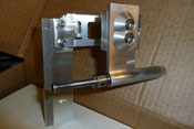
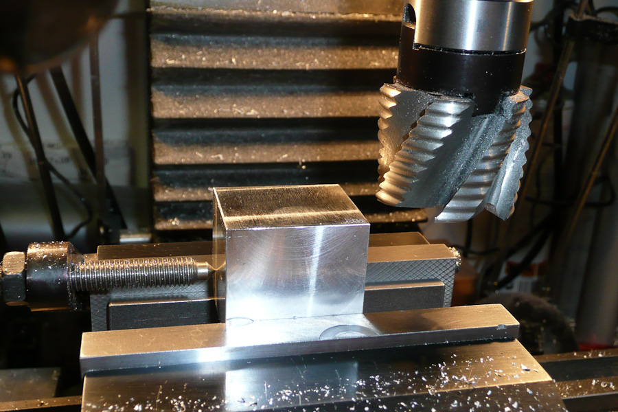
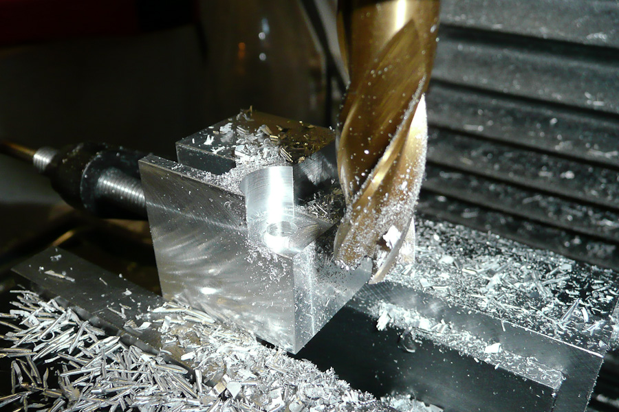
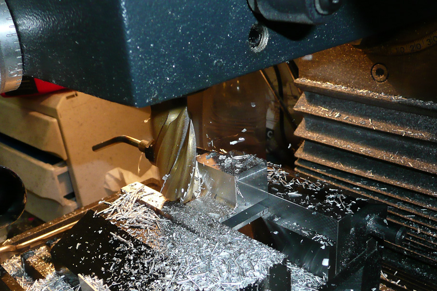
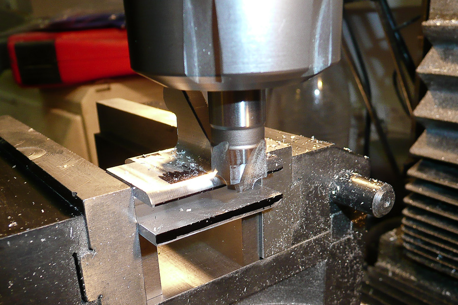
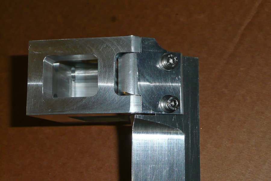
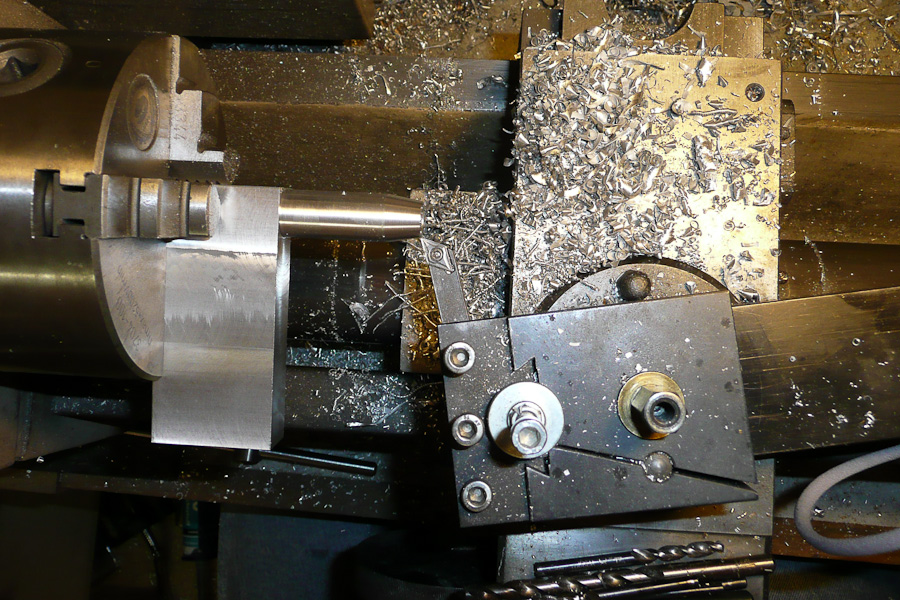
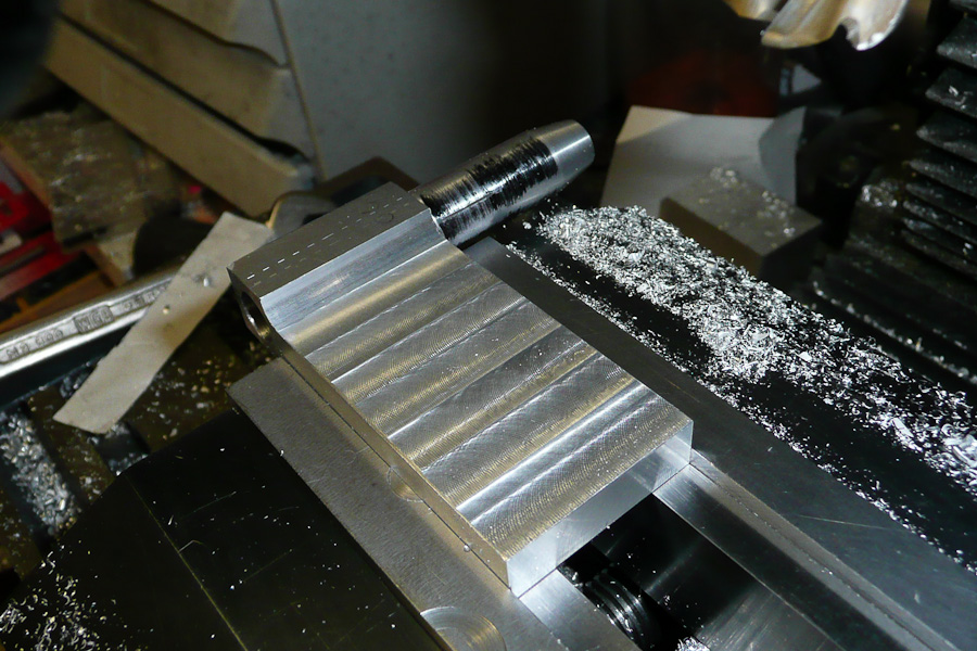
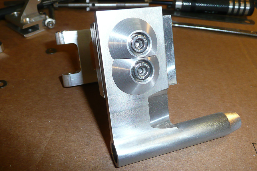
I started with the hinge for the rudder blade (this is commonly refered to as a "bearing block"). First I have to make a rectangle block with the outside dimensions of the hinge. I use a big cutter on the milling machine for that. It produces really smooth surfaces. It looks easy but it is a lot of work because you have to work on all 6 sides. So the rule here is think thrice, measure twice and cut only once!
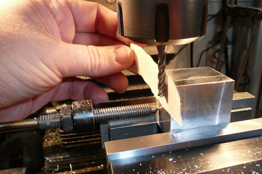
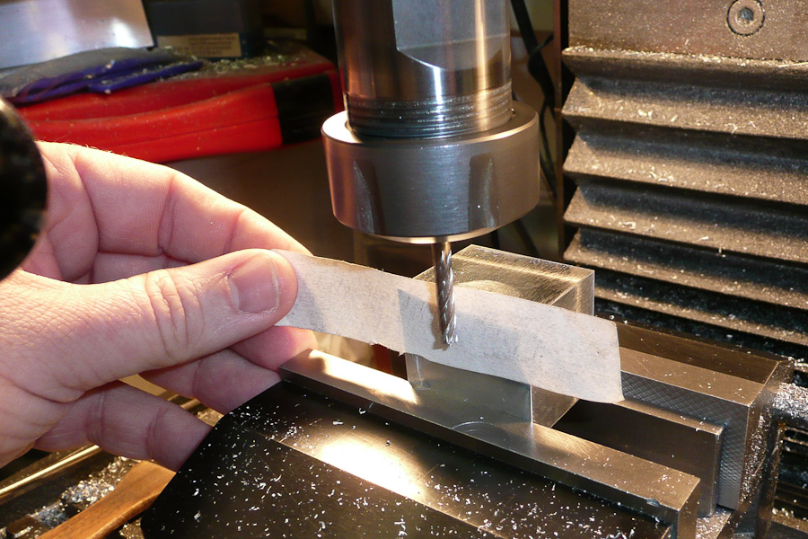
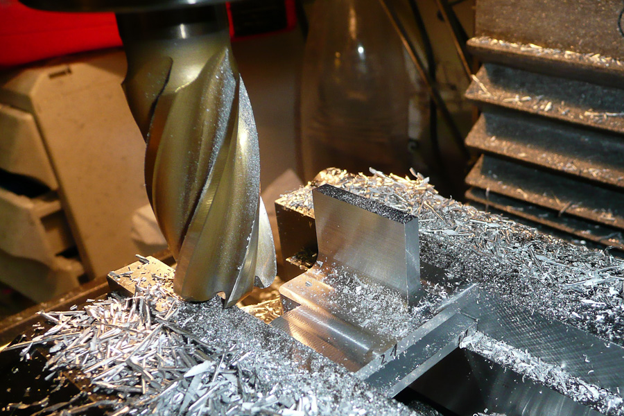
The next step is to cut the slot for the rudder blade. The rudder blade will have a thickness of 6mm. To make the slot I use a long 5mm cutter. To find the exact position for the slot I clamped the aluminium block into the vise by using an arrester as fixpoint. After that I bring the cutter close to the aluminium block. Between cutter and the block I hold a piece of paper with a thickness of 0.1mm. When the cutter touches the paper it will twitch the piece of paper out of your fingers. Now you know that the cutter is exactly 0.1mm away from the block without making any marks on the smooth surface! It is easy now to bring the cutter to the exact position you want by using the scales on the handwheels.
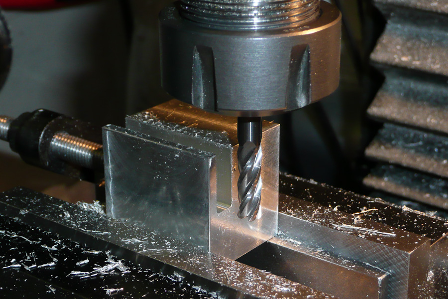
The cutting of the slot is a slow process because you can only cut 1mm deep on each pass.
*BTW: I use a carbide cutter for this job. It has rounded tips, so I avoid stress points on sharp edges.
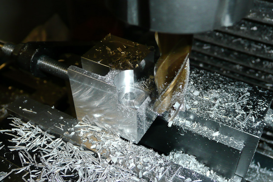
When the slot is deep enough I widen it on both sides up to 6mm. This way I get smooth surfaces on the inside walls of the slots without any chatter marks.
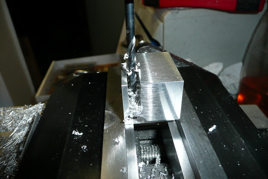
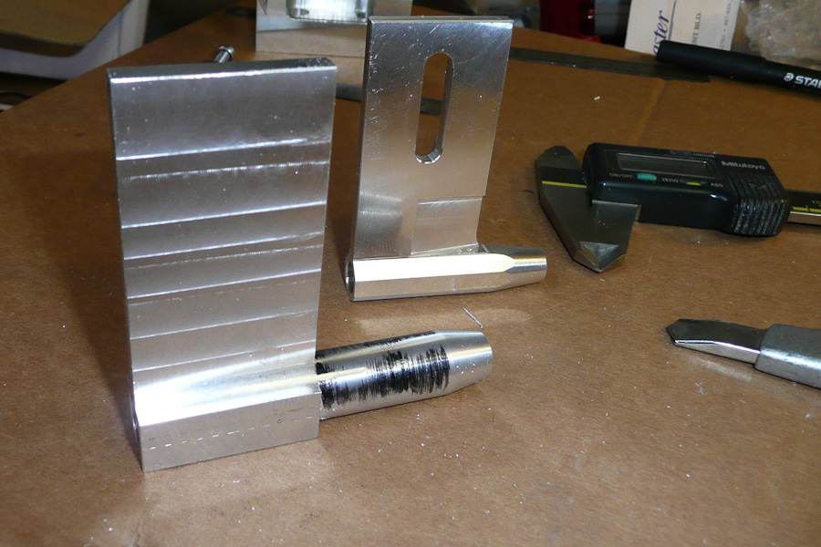
The next step is drilling the hole for the rudder's pivot pin. Very easy...we just need a drillbit. I use a 5mm stainless steel pin for the pivot.
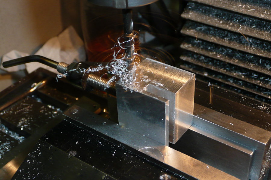
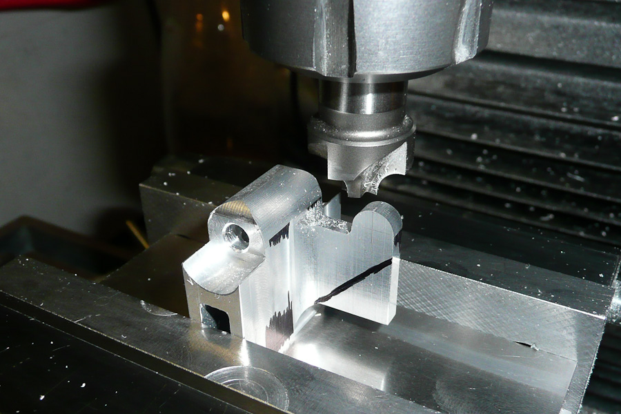
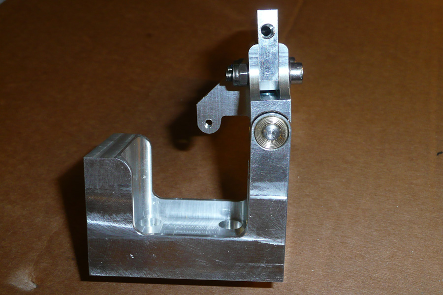
After that I remove material around the pin area for the bearing carriers of the rudder bracket. I cut up to half the diameter of the position of the rudder axle. To get enough space for the bearing carriers I cut a 12mm semi circle from the top and also from the bottom. At this stage it looks crazy but when all parts are ready and assembled it looks great (for me…)!
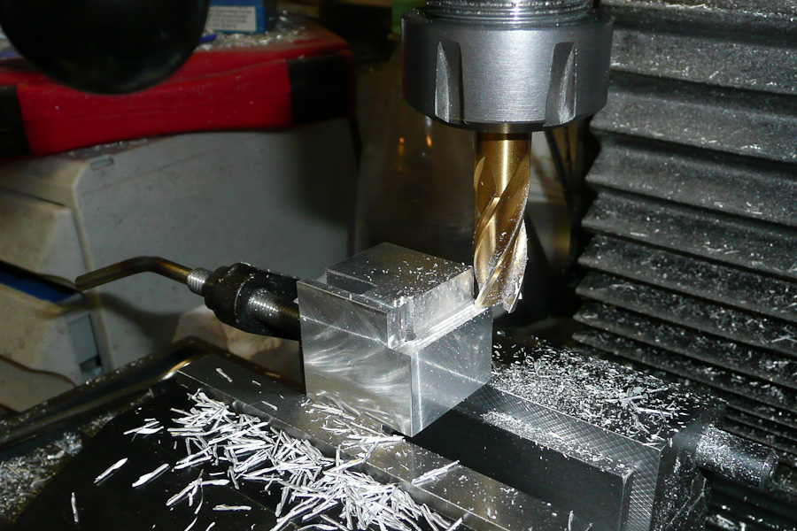
The following step is easy; just drilling 2 holes 4.2mm in diameter and cutting M5 threads for the set screws to lock the pivot pin in place in the block. To get a smoother finish on the hinge I round the tips of the pin support with a quarter circle cutter.
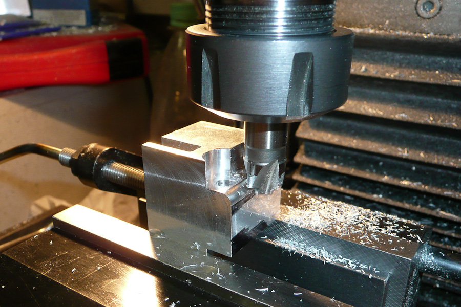
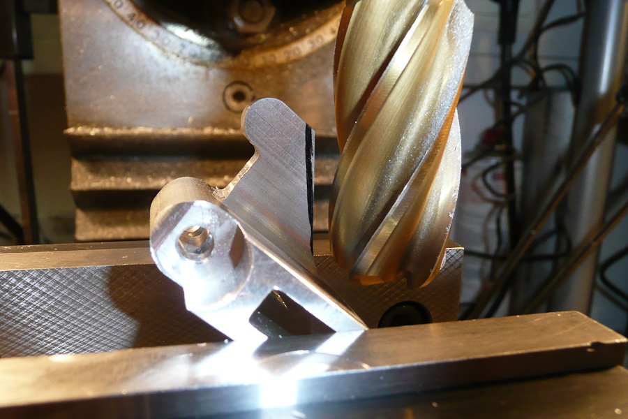
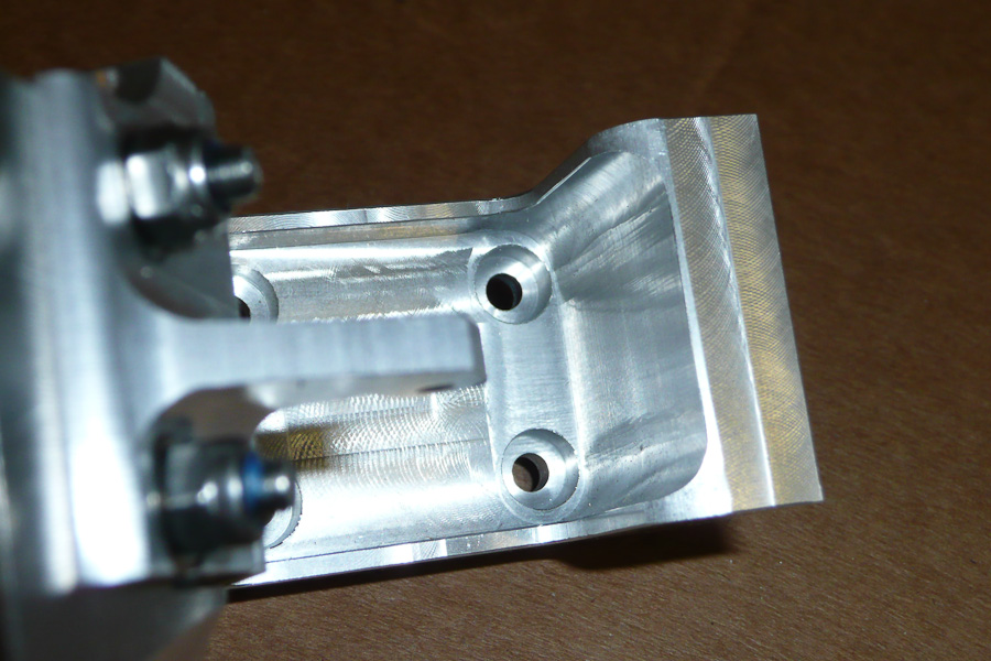
Now it is time to make some more chips: The rudder hinge gets an integrated rudder horn. I just have to remove all the material that isn't to be part of that horn. I use a cutter with a 22mm diameter and rounded tips with 3mm radius. This is my most often used cutter. It creates smooth surfaces with a nice intersection.
After these steps you have a strap for the horn. But it is a lot of work involving the use of different cutters to get the final shape of the rudder horn. I try to avoid sharp edges or intersections, so the use of cutters with rounded tips or quarter circle is necessary.
I also rounded the edges on the backside of the hinge. After that I removed some material from the top. This is more for the look than it is a necessary detail.
The last step is to drill the holes for the scews to hold the rudder blade. I use M4 stainless steel screws for that. The top screw is the pivot point for the rudder blade when hitting something in the water. The lower screw jams the rudder blade into the hinge. For this screw the rudder blade has a slot instead of a hole, so that the rudder can kick back without breaking screw (unlike the brass screw setup that is used on Speedmaster rudders).
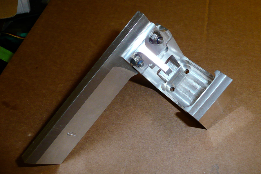
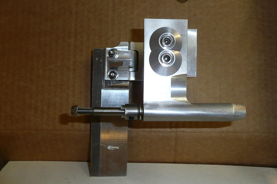
I don't have pictures of the making of the complete bracket or the rudder blade but I hope you get an idea of how it's made by checking the pictures of the complete unit.
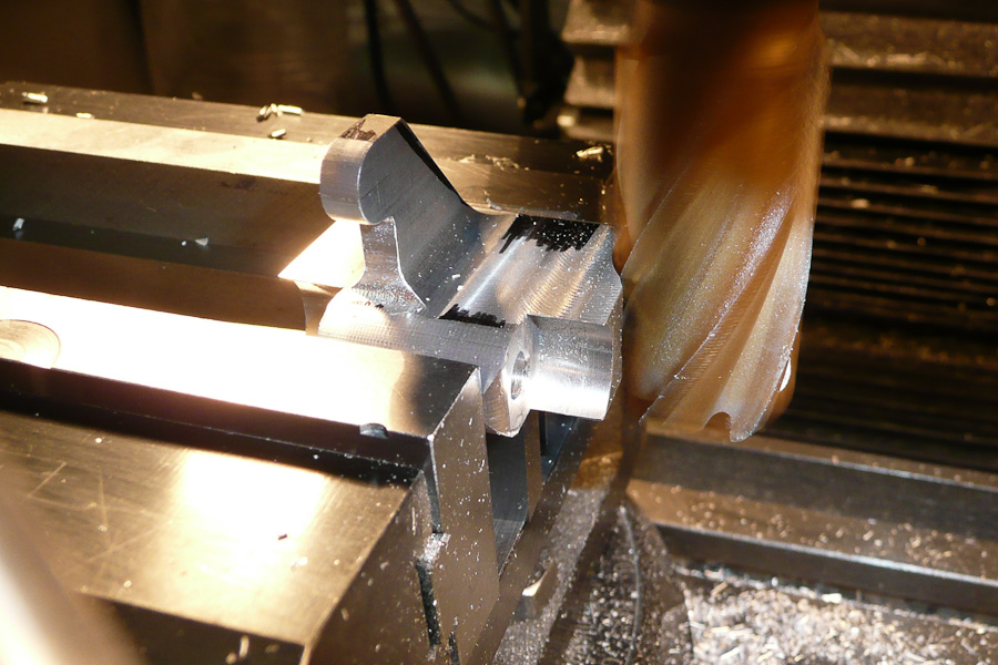
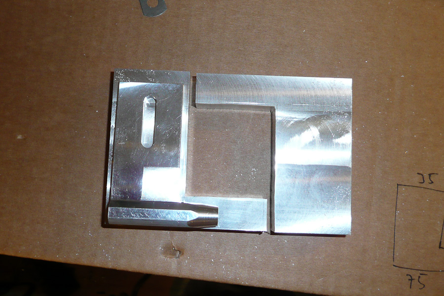
The next part that I have to make is the strut.
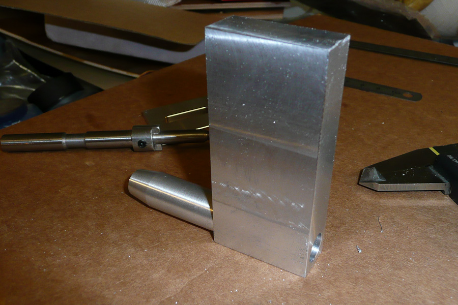
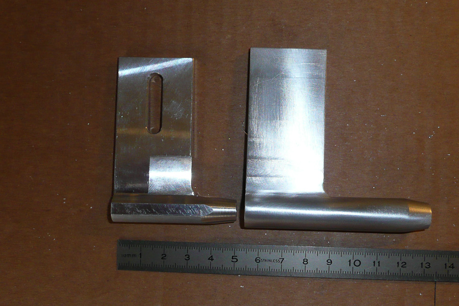
In the first picture you can see the first aluminium parts cut out of a solid piece of aluminum. These parts are shown in comparison with a Speedmaster strut blade.
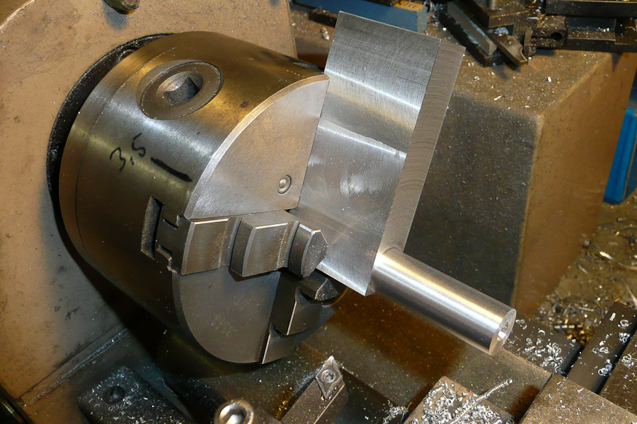
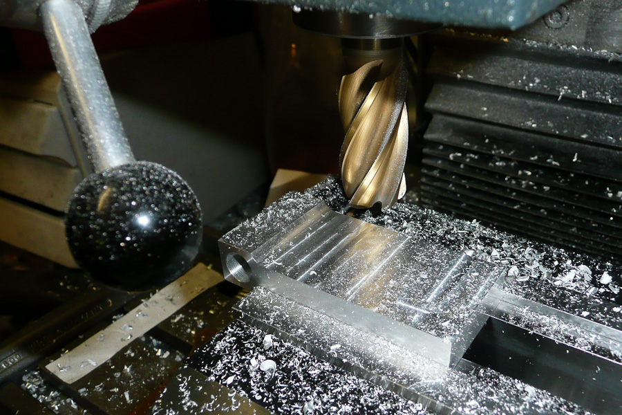
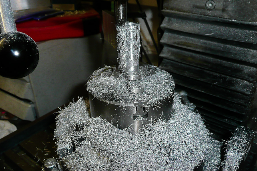
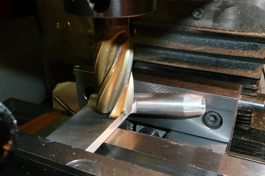
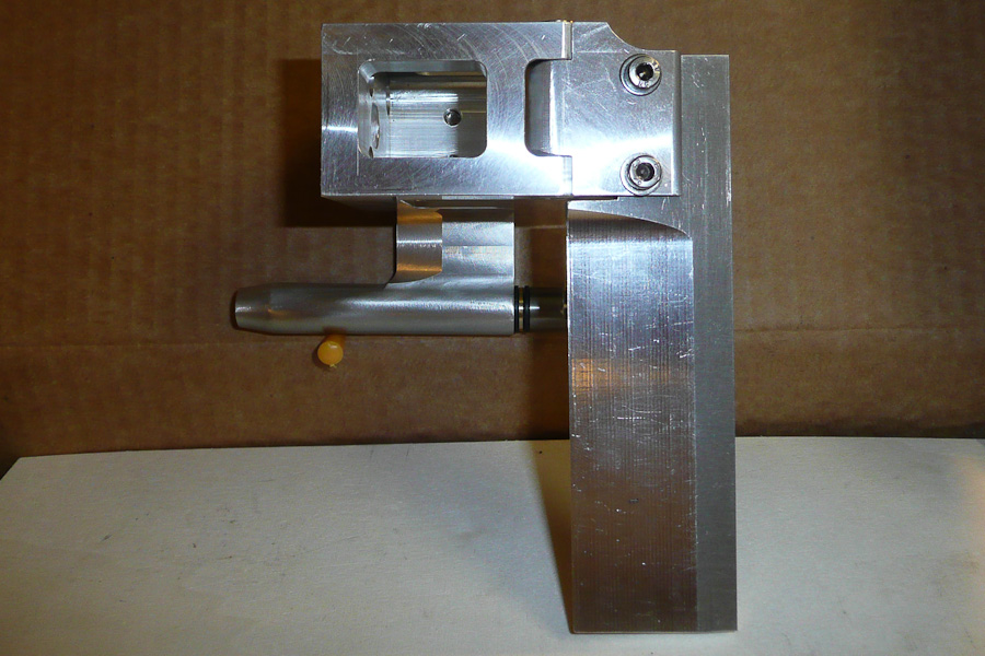
The next step is to make the short boom of the L-part round (the barrel). I use a four-jaw chuck on my lathe, remove one of the jaws to fix the strut to the chuck. I also tapered the nose of the strut for where it meets the stuffing tube. After that I made the bore for the bearings, drilling with a 9.9 mm drill bit and widening it with a 10.0 mm reamer.
Now it looks a little bit more like a strut and not just an “L”... but it is not ready yet.
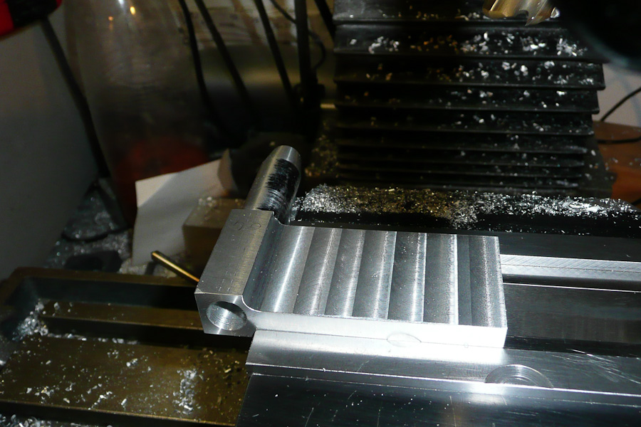
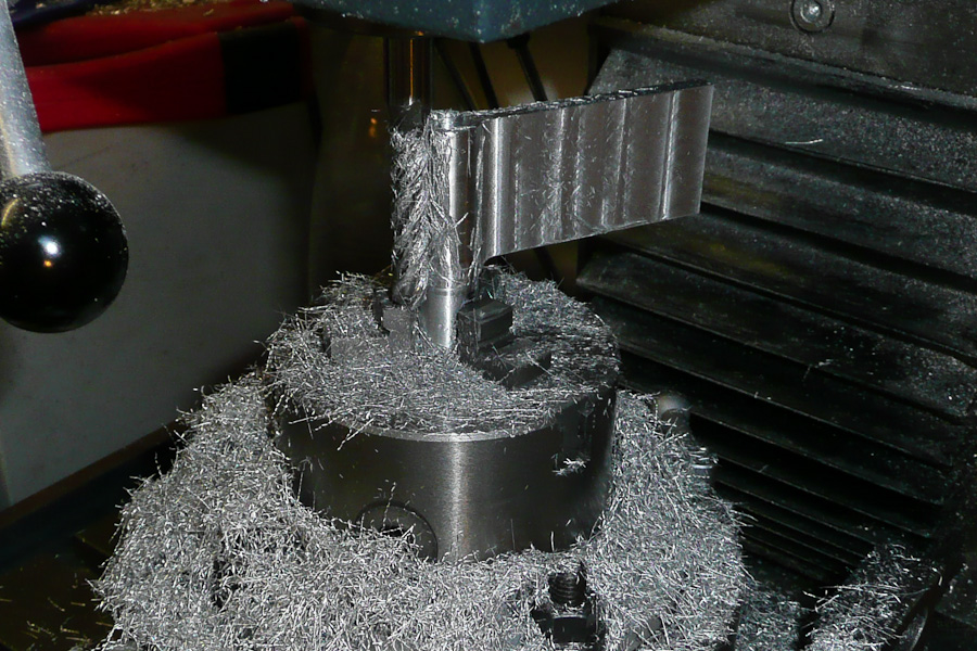
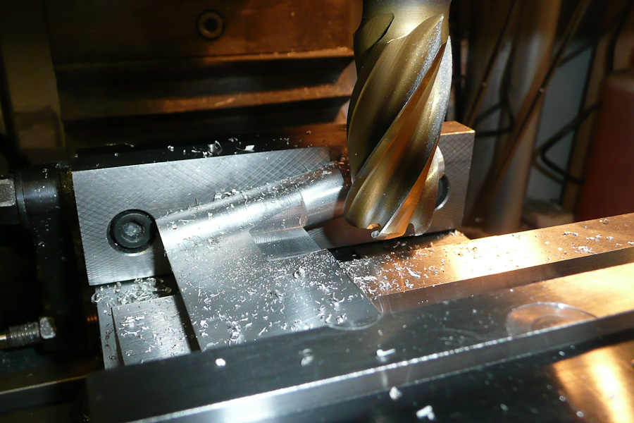
After that I had to flatten the mounting strip. I use the big cutter with the rounded tips. This step looks easy but it is a lot of work! I don’t want to hit the round part of the strut but do need to get as close as possible to it. You have to cut very carefully and it's hard work for your eyes!
Now the part looks really looks like a strut.
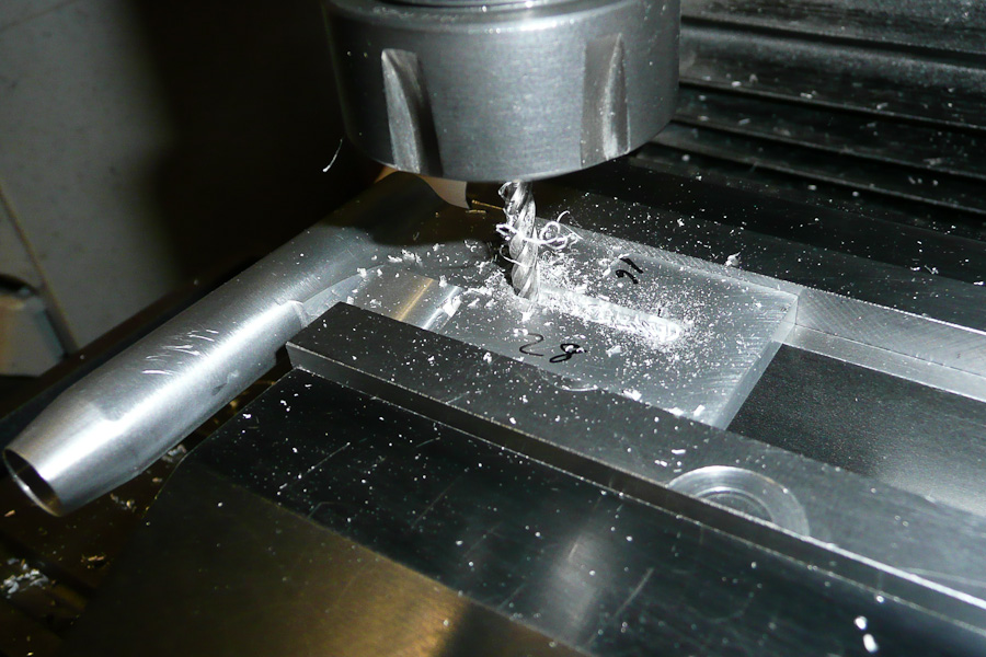
The next step is one of the hardest...making the strut completely round! I do this with the help of a rotary table on the milling machine. The cutter has to be very long and you can only run the machine at low RPM cutting only thin layers at a time. Otherwise you will, at best, have nasty chatter marks on the finished strut or quite possibly even destroy it completely! The trick is to cut up to the rounded part of the strut and as close as possible to the mounting strip. After all that machining I “clean” the strut with a fine sanding fleece to remove scratches.
Adding sharp edges on the leading edge and a slot for the bolts are now easy steps.
For the bolts I made 2 big angled washers and cut both on one side. I like the look of that, it makes it unique.

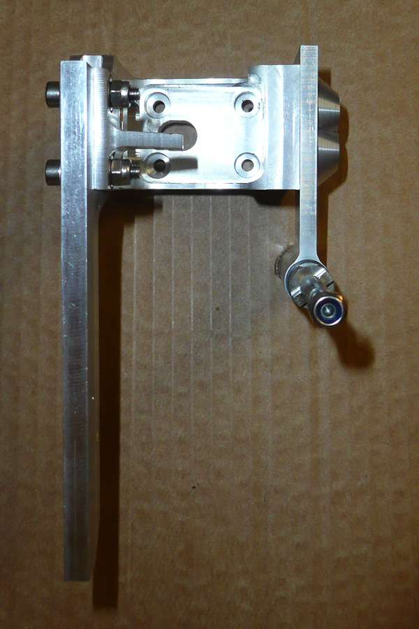
The complete unit is mounted to the hull with only four bolts. All measurements exactly match the recommendations from Brian Blazer.
I spent many evenings building this drive and rudder assembly but I think it is worth all the work...this kind of stuff is a big part of the hobby for me!
André

") .
.