

In this short article we will explore the methods of properly "tuning" a Tuned Pipe system to your engine.
Numerous
times I have seen people ask for the magic length for a particular tuned pipe
system. The truth is that the "ideal" length is dependant of many
factors. Things such as engine exhaust timing, type of boat, intended
application for the said boat, propeller used, type of drive system, weather
conditions, etc. So many things can affect something else that tuning must be
done for the combination of hull, hardware, engine, pipe and prop as a whole.
There is no way around this if you are looking for optimum performance from
your boat. You can tune the pipe to the engine for a specific RPM range, but
the ideal RPM range can change depending on the factors mentioned above.
In this article we will assume that everything other than the pipe's tuned
length itself has been decided and can not / will not be changed, just to explain the basics of tuning the pipe.
We will also assume that the tuned pipe system being used has been well
designed for the engine. In real life, you must remember that you will have to
experiment with different propellers, drive settings, etc to get the best
possible performance from your boat...and every time you do so, you might have
to re-set your pipe to get optimum performance for the combination you have
chosen. Tuning a pipe for best performance at a said RPM range on a dyno and
setting a pipe for best on-water performance are two different things. We want
to set it for best on-water performance.
So let's start with what the tuned pipe does and why we need to
"tune" it.
For more detailed theory on how a tuned pipe works scroll
down in this article and read "How Two-Stroke Expansion Chambers
Work".
Here
is the simplified explanation, the way I see it.

Now in order to maximize this "supercharge" we must tune to pipe so that it does this "push/pull" at the correct times during the stroke. Since we are usually working with a fixed expansion chamber, the only thing we CAN adjust is header length. Some pipes have adjustable stingers, but this will not be covered.
Here are my recommendations for setting a tuned pipe system for the commonly
used Zenoah G260PUM engines:
* please note these are only recommendations. They are for DRY TUNED PIPE SYSTEMS ONLY. You can start with longer or shorter header settings if you wish.
If the manufacturer of the pipe can give you a recommended starting length follow his recommendations.

After
you have measured and set the pipe for the starting adjustment of 13",
mark the header and cut it so no more than about 1/2" extends inside the pipe past the second Oring. If you are using a steel pipe then cut it so you have the least amount possible extending into the chamber. See picture further in this article.
With the pipe setup at starting length, run the boat and note performance. Ideally you need a Tachometer installed in your boat for testing and a GPS isn't a bad thing to have also if you want to know actual speed. With experience you can do most of the initial testing by ear and sight but in the end the Tach and GPS are indispensable in my opinion.
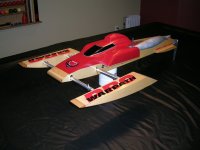
When using aluminum pipes with water-cooled couplers, you should find a means of preventing the pipe from moving on the header. Pictured below is a pipe clamp that does just that.


After a good run, bring the boat in and note the speed and RPM readings. Now
push the pipe in on the header, making it about 1/8" shorter. Run the boat
again. Again, note speed and RPM readings. Also note how the boat performs on
water. In the end it's not necessarily just about top RPM and top speed...it's
also about the kind of throttle response and acceleration you want.
Keep shortening the pipe combo 1/8" at a time. In my opinion to do this
correctly you should try and keep the part of the header extending into the pipe
as short as possible. So in reality you should be cutting off the header every
time you shorten the pipe. With water-cooled couplers such as found on aluminum pipes you may want to have it extend a little more than
normal just for testing, but still keep it as short as you can. Keep it about
1/2" - 5/8" extending past the second Oring during testing.
Continue shortening the pipe and running the boat, every time taking notes on
speed, RPM and performance. Do this until performance starts degrading. At this
point you will back the pipe out to the previous length, to where it performed
max before starting to go downhill. You can now trim the excess header inside
the pipe if necessary. I usually keep it to 1/2" maximum past the second Oring. Headers are
relatively inexpensive, so you can keep spares in case you have to run it
longer on a different setup. If you have too much extending inside the pipe it
will affect performance.
In the picture below you can see approximately where to trim the header. On a steel pipe you should try to trim it so none of the header is actually extending inside the diverging cone. On an aluminum pipe with water-cooled coupler, you must note where the Orings are and make sure the header sufficiently clears the second Oring for proper sealing.

You have now set your tuned pipe system for optimum performance with your boat
setup! Easy isn't it?
In theory this should never change after you have set it, but in real life conditions
you might find the need to lengthen it for a bit more torque or shorten it for
more RPM. One is at the cost of the other unfortunately!
For example if you change to a propeller that puts more load on your engine,
you might have to lengthen the pipe a little bit to get the required added
torque. The pipe in this case will tune to a lower RPM range. If you change to
a propeller that puts less load on your engine, you might want to shorten the
pipe a little to gain more RPM since it is now requiring less torque. The pipe
in this case will tune to a higher RPM range. This is what I was talking about
earlier when I said many factor affect the "optimal" tuned pipe
length for your setup.
Happy Tuning!
Read on for more technical information on tuned pipes!
How Two-Stroke Expansion Chambers Work
*This information is from
Dave Marles of Prestwich Model Boats .
You know that changing the exhaust pipe and pipe
length on your boat can have a marked effect on the engine's power
characteristics, but do you by how much and why ?
How Much. A two stroke 125cc engine with standard exhaust system can
combust no more than 125cc of fuel air mix. A two stroke 125cc engine with good
tuned exhaust system can combust approx 180cc of fuel air mix.
Why. Simply put, it's because the two-stroke exhaust system,
commonly referred to as an 'expansion chamber' uses pressure waves emanating
from the combustion chamber to effectively supercharge your engine.
In reality, expansion chambers are built to harness sound waves (created in the
combustion process) to first suck the cylinder clean of spent gases--and in the
process, drawing fresh air/gas mixture (known as 'charge') into the chamber
itself--and then stuff all the charge back into the cylinder, filling it to
greater pressures than could be achieved by simply venting the exhaust port
into the open atmosphere. This phenomenon was first discovered in the 1950s by
Walter Kaaden, who was working at the East German company MZ. Kaaden understood
that there was power in the sound waves coming from the exhaust system, and
opened up a whole new field in two-stroke theory and tuning.
An engine's exhaust port can be thought of as a sound generator. Each time the
piston uncovers the exhaust port, the pulse of exhaust gases rushing out the
port creates a positive pressure wave which radiates from the exhaust port. The
sound will be the same frequency as the engine is turning, that is, an engine
turning at 24,000 rpms generates an exhaust sound at 24,000 rpms or 399 cycles
a second--hence, an expansion chamber's total length is decided by the rpm the
engine will reach, not displacement.
Of course those waves don't radiate in all directions since there's a pipe
attached to the port. Early two strokes had straight pipes, a simple length of
tube attached to the exhaust port. This created a single "negative"
wave that helped suck spent exhaust gases out of the cylinder. And since sound
waves that start at the end of the pipe travel to the other end at the speed of
sound, there was only a small rpm range where the negative wave's return would
reach the exhaust port at a useful time: At too low of an rpm, the wave would
return too soon, bouncing back out the port. And at too high of an rpm, the
piston would have traveled up the cylinder far enough to close the exhaust
port, again doing no good.
Indeed, the only advantage to this crude pipe system was that it was easy to
tune: You simply started with a long pipe and started cutting it off until the
motor ran best at the engine speed you wanted.
So after analyzing this cut-off straight-pipe exhaust system, tuners realized
that pressure waves could be created to help pull spent gases out of the
cylinder. Following this, The tuners realised that these pressure waves
could be utilised still further by using a divergent cone to increase the
strength of the negative wave and then that a convergent cone added to this
would increase power still further as explained next....
The exhaust opens on the down stroke
and a pressure wave emanates from the exhaust port into the header pipe. This
pressure wave travels through the exhaust gases that are in the pipe at the
speed of sound... It’s the pressure wave that travels at this speed, not the
exhaust gases themselves. (Imagine a stream and you throw in a rock. The waves
from that rock will travel down the stream faster than the speed of the water.)
Anyway, the wave reaches the front divergent cone and a weak negative wave
(negative pressure or ‘suck‘) (laws of physics) is sent back to the exhaust
port which reaches the exhaust port while the transfers are open helping to
remove exhaust gases from the cylinder which in turn helps fresh mixture from
the crankcase up through the transfers into the cylinder. (Some of which will
enter the front part of the header)
The length of
the front cone and its distance from the cylinder (header length) determines
the amount of time that the pressure reducing wave from the exhaust does it
work in emptying the cylinder of exhaust gas and then assisting the fresh
mixture up from the crankcase into the cylinder. If header is too short then
the wave energy from the front cone is wasted because the negative wave (the
‘suck’) arrives at the exhaust port while the cylinder pressure is still high
after combustion. It should arrive there when the pressure in the cylinder is
low but there are still exhaust gases that need to be extracted. If the header
length is too long then the wave is arriving later than optimum and the exhaust
gases are not fully removed from the cylinder. The front cone needs to be long
enough to generate a wave to help the fresh mixture into the cylinder but it
also needs to continue working long enough to allow some fresh mixture into the
first part of the header. This is the mixture which will be forced back into
the cylinder. If it is too short, then it does not allow mixture into the
header. If it’s too long, then it reduces the length of the rear cone and that
needs to be long enough to force all of the un-burnt mixture in the header to
be forced back into the cylinder. The pressure wave continues into the rear
cone and immediately sends a positive pressure wave (laws of physics!) back
down the tuned pipe towards the exhaust port forcing the un-burnt fresh mixture
back into the cylinder. The strength of the wave increases as the rear cone
gets smaller and the length is made so that the returning pressure wave from
its very end at the junction with the stinger coincides with the point of
exhaust port closure. When this most critical length
(start of stinger to exhaust port) is correct, then maximum power is achieved.
If this critical length is too short then the returning wave forces hot gases
back into the cylinder, dramatically increasing cylinder combustion
temperatures. If this length is too long the maximum power will not be achieved
because maximum supercharging or cylinder filling will not occur, although
power in the corners will be better because the tuned length will coincide more
with the reduced rpm in the corners.

The tuned length L as shown in the diagram is the length that most people use as a comparison. This is OK as a comparison but the length that is most critical is TL. Many different pipes can be used on an engine but that tuned length TL will always remain the same within a few millimetres for a specific rpm (if all other factors remain constant, nitro content, oil content, air density, temperature etc). This applies to all two stroke model engines, petrol (gas) or Glow powered (nitro). We know this from many, many bench and on the water tests conducted on many different engines. To elaborate: If you were running a tuned pipe at its optimised length (the length that is giving most power or speed) and that pipe had no flat in the centre section and you wanted to change to a pipe with a flat in the centre or belly section. You should measure TL on the old pipe and then set TL on the new pipe to the same length to give you a starting point for adjustment.
TUNING THE EXHAUST SYSTEM
Pipe length is decided by rpm, exhaust timing and speed of sound within the exhaust system. The last part should remain almost the same whatever you do to the exhaust timing or rpm.
1. If you increase the exhaust timing and rpm stays the same then pipe length is longer.
2. If you increase the rpm but exhaust timing stays the same then the pipe length has to be shorter.
If you can measure the rpm of your motor and exhaust timing, then you can use a simple calculation to show how much you need to change the pipe length when altering ex timing and rpm. Here are some simple calculations for gas engines where the exhaust gas temperature is not affected by nitro content and varying fuel settings.
(For these calculations you can measure the pipe length between whatever points you want to, but the norm is from plug to widest part of cone.)
Pipe length from manifold face to widest part of front cone. = L
Exhaust timing = E
Constant = K
rpm =R
If rpm is 15,000, exhaust timing is 175degrees (duration) and pipe length is 13" then....
Firstly you work out the constant for your set up. So...
K = R x L K = 15,000 x 13 = 11.14"
------------------ -----------------
E 175
In this example that would give a K number of 1114 and as I wrote before, K will remain the same whatever you do...
If you want the engine to rev at 16,000, the equation changes to...
L= E x K therefore L = 175 x 1114 = 12.18
------------- ---------------
R 16,000
This would make the new pipe length 12.18" or 309mm.
If you wanted to increase exhaust timing to 180 degrees and run at 17,000rpm then the length L would be 11.79" or 302mm.
STINGERS Stinger length should be separated from stinger diameter because although they are linked, in practice you would need to make a big change in stinger length to affect the backpressure. Stinger diameter is crucial to the pipes operating temperature and hence the power production. If the stinger is bigger than optimum them making it even bigger will have little effect but by sleeving it down then you will be able to find the size that gives best power. Normally a smaller stinger will improve top end power because the exhaust gas temperature will increase which will have the effect of a shorter pipe length. If you go too small on the stinger then power will suddenly start to drop in the corners and the motor will begin to overheat. To get the best power it’s usual to lengthen the header and make the stinger smaller to get the best overall performance. A bigger stinger will have the effect of spreading the power band but the engine will not make the same peak hp.
Stinger length is important because its part of the pipe resonance. The wrong stinger length will reduce performance at the upper end of the rpm band. i.e. between peak torque and peak bhp... There will be maybe one or two stinger lengths that will cut the rpm off at a certain level reducing the 'overrevv' which gives the best top speed. There will be one stinger length which gives the best overall power and over-rev. I find no way to calculate that stinger length, trial and error is the only way. It’s not dependent upon engine size, just on the pipe design. For example, my best .21 pipe runs over 100mm stinger but my best .90 runs around 60mm. One thing though, very short stingers up to 20mm long don't normally work and extremely long stingers of 150mm to 200 mm can work very well. Once the best stinger length is found, it does not seem to vary if the pipe length is altered.
PS On stinger length, it’s only a few percent performance difference but every little helps!! The speed of sound within the exhaust system is dependent upon the EGT (exhaust gas temperature). The higher the temperature the longer the pipe length must be for a given rpm... EGT will vary with these factors. Stinger diameter (smaller stinger = higher EGT), fuel needle setting. (a leaner mixture will raise EGT.) Fuel mix. High oil content reduces EGT; High Nitro content also reduces EGT.
A few helpful facts. The volume of a pipe is only really related to the displacement of the engine because the various diameters of the pipe (header, belly and stinger) are a function of exhaust port area, and if an engine has a bigger displacement, it usually has a bigger exhaust port area. It's often said that a bigger volume pipe is less peaky or it has a broader spread of power. This is not actually so. The volume takes care of itself when the pipe is calculated. The important things are firstly (and most importantly) the length from piston face to start of stinger and secondly header length, cone lengths, belly length, and then header diameter, belly diameter and stinger diameter. Normally a good pipe will have a belly cross sectional area of about 10 times the exhaust port area with a stinger diameter of about 0.5 to 0.6 of the exhaust port area and the header around 1.2 times exhaust port area. By exhaust port I mean the actual port in the liner not the port where the exhaust manifold bolts on. If we take 2 pipes with the same cone lengths and total tuned length then the pipe with the largest volume will require a smaller stinger diameter to maintain the same EGT (exhaust gas temperature) within the pipe.
")