
Tech Article...by Scott Schneider
A step-by-step tutorial on how to modify an RCMK S/SX 254 Engine ... *All R254 Cylinders
To begin, I wish to make it clear that many of the designs and fundamentals being shared herein have been learned from published sources of information as well as from self-taught tricks. The working blend of modifications presented are from many years of trial and error testing while working with small displacement 2-stroke engines.
The use and application of this knowledge being applied to the RCMK engine is what we hope to share here.
Information as presented, will be worded simple and to the point. If you don't agree with or understand what's been said, please feel free to share your insight or questions with the community within the MGB forums. A link is provided at the bottom of the article.
Note: Many of the modifications being done look very close to what was being done within the Zenoah G-260 “Engine Porting” article, but they differ in enough ways that you need to take notice of the explanations contained at each step.
Let’s get started. Disassemble your RCMK engine and follow along. This should help you "do-it-yourself" engine modifiers build a very powerful RCMK marine racing engine.
Crank Case and Crank Shaft ...
*This step is optional, "Turbo Crank and Cases mod". (Used ONLY with side exhaust designs)
** What a “Turbo Cut” modification does is redirect the air/fuel outward as the crank spins within the cases.
 |
| Here is what the Modified Turbo cut of the crankshaft's leading edge counter weights looks like. |
As the crank spins, the displacement of air/fuel is directed outwards towards the crankshaft main bearings aiding in their lubrication. As the leading edge of the modified counter weights clears the inner case entering the transfer passage cut away, the displacement of the air/fuel is directed into the flow that is headed up the transfer passages. Another benefit is that by controlling the air/fuel within case area, the engine has less crankcase fuel pooling and tends to load up less and run cleaner when coming up from lower RPM. (Only the leading edges of crankshaft’s counter weights need to be modified.)
* Each case half gets a further enhanced trough cut into the case at the leeward edge of the rotation side.
* The crankshaft’s leading edge counter weights get ground into a slight bevel/sloping wedge profile. (Nothing any more radical than shown is necessary.)
|
|
 |
 |
| Here the PTO half of the crankcase. The larger trough cut into the side of the case is blended into the cylinder mating surface. The flywheel side case half is done the same. (Note the bearing covered with tape on both sides to keep metal chips out.) |
To make the blending easier, place 2 scribe line as shown on cases, blend in the turbo ramp cut up to these lines as shown in the picture on right. | Here both halves showing the blending of the trough into the mating surface of the cylinder. * The gasket as shown to the right needs to be trimmed to fit this new profile * |

Piston ...
The piston requires no lightening, just a simple rounding of the pin boss area so the air flow into transfer passages is smoother.
 |
|
| Here the rounded profile done on both pin boss areas of piston to smooth the flow out. * Do smooth out better than shown.... |
* This is the OPTIONAL intake duration modification....approximately 0.035" was removed from the middle area of the "Intake Side" piston skirt. The corners of this cut need to be kept ROUND! The little tabs of material on either side are there to maintain the original length of piston and hold the diameter to factory specs. ( Piston is Tapered, so this type cut is required ! ) |
* This next step is for those wishing to explore the upper RPM range power gains of GREATER intake duration.
This modification is done by altering the intake side skirt of the piston and NOT cutting on the cylinder!For the basic modification, omit this step and run your modified engine first. You can easily go back and do this step if you need or choose to.
As shown in the picture, the safest and most structurally sound way of doing this is to only remove a portion of the skirt leaving material on either side. (This maintains the original piston length, aiding in having less piston rock, and in cases of the tapered "S" series engine piston, maintains the stock diameter for a better seal. (Keep the corners rounded so that these little outside tabs are less prone to fatigue.) Intake duration on a STOCK S-254 engine is @ 151 degrees. Doing the intake skirt modification removing @ .035" brings the intake duration to @ 158 degrees.
Cylinder ...
This process very closely follows the Zenoah modifications but does differ in the cutters being used and in the desired shapes and direction changes made at the transfers’ outlet windows.
Starting with a 1/4" shank ball end cylinder cutter, carefully cut two vertical slots into the intake side transfer passages next to the intake port. (Leave a 3/32" or greater margin of chrome between the cut and cylinder bore.) Make this cut all the way down to the roof of the transfer port making sure the depth and size/shape of this cut is the SAME on both sides.
Next make note the shape of the factory entry angle and the wedge of material within the transfer window on the center divider side. This you MUST maintain and not hit or remove it! (Dentistry pick pointing to it.)
So we use a 1/8" shank cutter with a 1/4" ball end. Carefully find the roof of the port with the cutter so that you know where to cut in the eyebrows on both sides.
** Note: the amount of eyebrow cut made. It is NOT excessive in length but it is specific in angle & shape. **
Once done, blend in the transfer passage so that when viewed from above, the side of the modified transfer passage blends into the eyebrow cut with no lumps or bumps.
 |
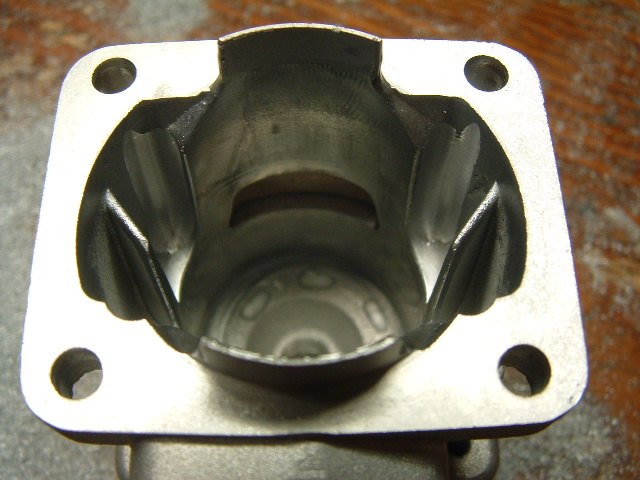 |
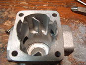
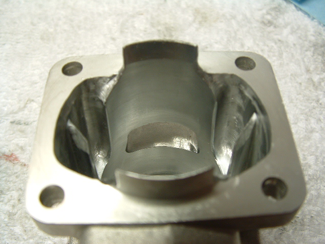
| Here the first cut made going down the inside edge of the INTAKE SIDE transfer passage. To be done on both sides. |
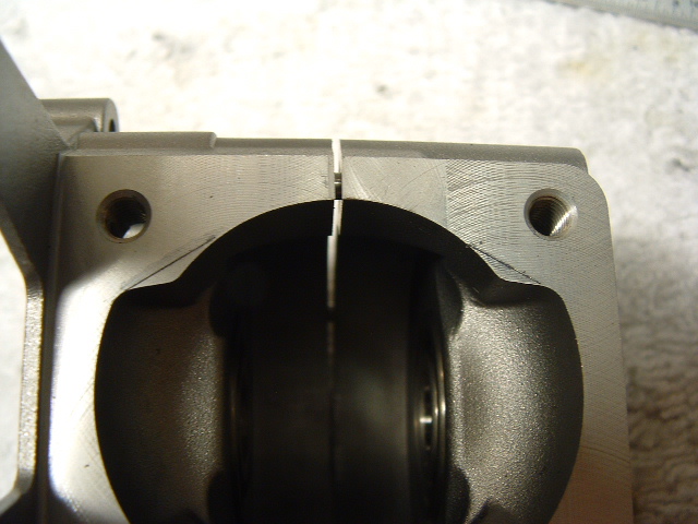
Top of the photo showing the "UNDERCUT" done to the edge of the EXHAUST SIDE transfer passages, bottom of photo the amount of cut made from picture on the left. |
 |
 |
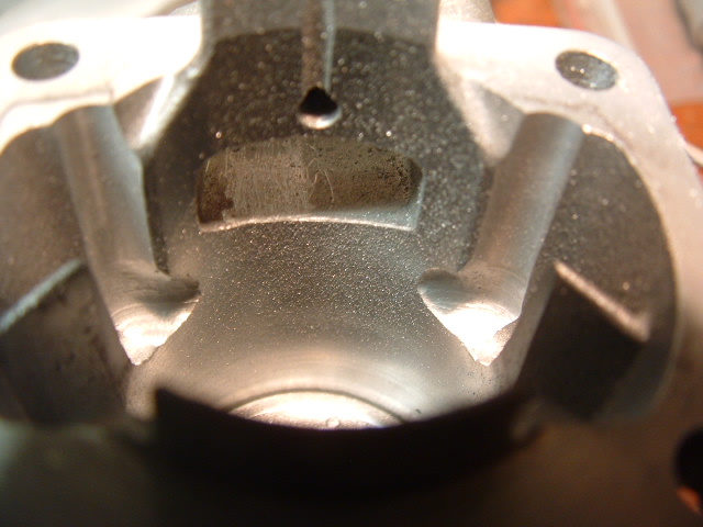
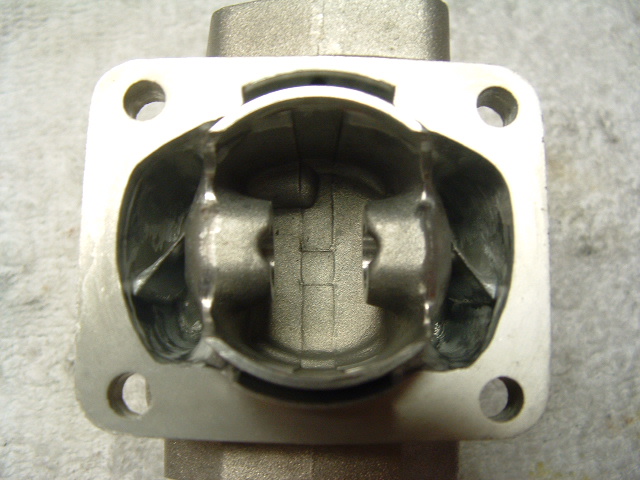
| Close up of the eyebrow cuts and 1st vertical cuts made on INTAKE SIDE transfer passage. | Here is the wedge of material cast into the roof of the divider, DO NOT disturb or hit if possible. |
 |
 |
 |
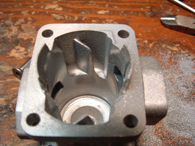
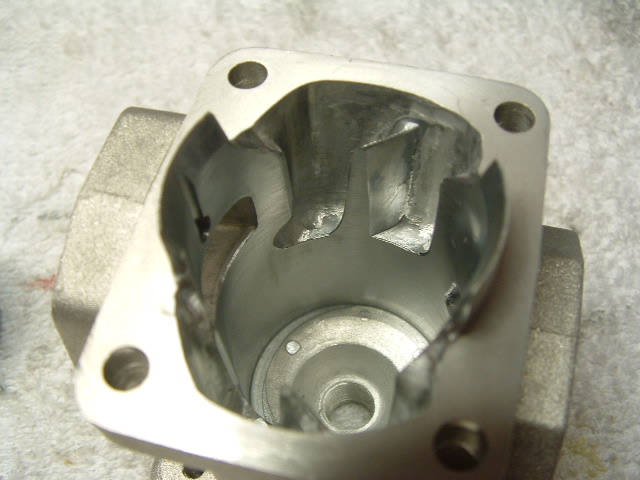
| The finished modifications on the transfer passages. Blended in with lead edge of divider sharpened. | Another view of the eyebrow cuts once blended in and finished up ... No lumps, No bumps ! | Finished up and blended in Undercuts of the EX side transfer passage. |
Note on picture above showing BOTH eyebrowed transfers:
* Their entry angle is set so that the outflow of air/fuel from each side collides about 1/8" - 3/16" away from rear cylinder wall...and NOT against it!
Note on last picture above with the dental pick noting the small wedge of material at the base of the transfer divider: This entry angle you DO NOT want to alter or hit while doing the eyebrows.
Next step: Using the 1/4" ball end straight cylinder cutter, undercut the vertical edges of BOTH transfer passages on either side of the exhaust port.
* This differs from the Zenoah modification in that we are NOT widening the outlet window but ONLY adding area to the passage, while slightly changing the air/fuel entry angle to be more directed towards the intake side of the cylinder.
|
|
|
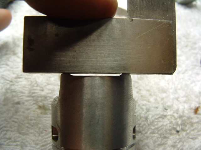
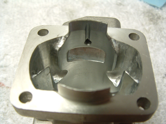
| Here is the amount of material removed in the undercut. You DO NOT contact the bore edge but stay in behind it. Take the undercut all the way to the port's roof. ** Be VERY precise in having the profile of the undercut the same on both sides. The intent here is that the outflow of air/fuel now is tilted slightly more rearward away from the exhaust port than stock. * Note the edge that the dental pick is on. If followed out into the bore it would be just behind the spark plug hole. Make sure this angle is the SAME on both sides! |
Here you now can see the increases in cross sectional area within the transfer passages. We HAVE NOT cut along the outside edges of the passages, only at both ends. Note: The angle on the edge of Intake side transfer passage (Top of photo), it should match the crankcases along the scribe lines of the turbo ramping blend in shown earier. |

The reason for this is so that the air/fuel traveling withing the transfer passages has to increase its speed at the point of exiting. This gives the ports' roof and general port shape greater control over the out-flowing mixture. This directional control is a MAJOR component in the shaping of the engine's power band.
Next ...
Using the 1/4" ball end cylinder cutter, cut the ROOF of the exhaust port into a gentle arched profile as shown. Very little if any material needs to be removed on the outer most corners. Most will be within the center area. You do NOT want to widen the exhaust port any further!
The best exhaust timing specification in my honest opinion on the RCMK engines is approximately 180 degrees.
* Due to RCMK changing specs on the parts in an ongoing basis for greater reliability, the EX 180* timing specs are best set using a degree wheel instead of a fixed dimentional number *
 |
|
| Here is the exhaust port roof profile you want. A gentle arch and NOT flat like stock. * No width increase is made, only the roof profile is altered. |
Here is a 1" CC Racing Engines "No-leak" manifold matched to the exhaust port. One HUGE outlet ! *Picture is upside down BTW. |

Next ...
 |
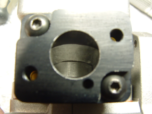 |
| Here the intake port with the ring compression nub removed. * Note: NO MORE material than required was removed at the actual intake port window. It is safer to actually leave a small lump of the nub. For safety sake DO NOT remove it all at the port window, you do not want ring to snag on the roof of the port if you over cut it! |
Here an after market aluminum intake block is fitted and matched up. The stock intake block is just fine also. Just match it up a little bit and you're good to go. |
NEXT ...
Attach your intake manifold to cylinder. Note where the cylinder's intake passage and the shape of the manifold differ and match them accordingly. Trim the gasket to fit as well.
FINALLY...
|
|
| Here the final trick ... Using a THICK flexible CA glue, you put a bead around the seal's outside diameter at the outer bearing race. This will help prevent a seal blowout while running at high RPM/ power levels. ** Clean with a STRONG degreaser such as MEK using an ear swab prior to glueing in the seal. |

Supplement
The steps below are 100% optional and are ONLY set up tricks preferred on my own modified RCMK engines.
* The reason for these modifications is to further stablize and more accuratly hold the connecting rod in the center of the crank shaft big end bearing.
In checking RCMK's machining tollerances, I have found that the engine is VERY square and true with the center line of the bore and the axis is perfect with the crankcase and cylinder's bolt pattern. Tightening up of the piston's "Small End" thrust washers can therefore successfully be done.
 |
|
 |
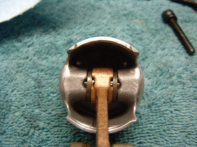
| Here is an assembled RCMK piston and needle bearing with the modified ZENOAH thrust washers. (Note: the piston skirt mod, this is the profile and amount of tab material left on either side.) |
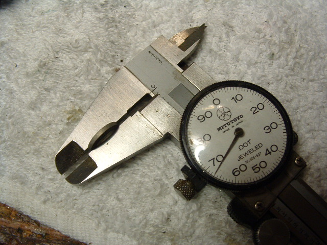
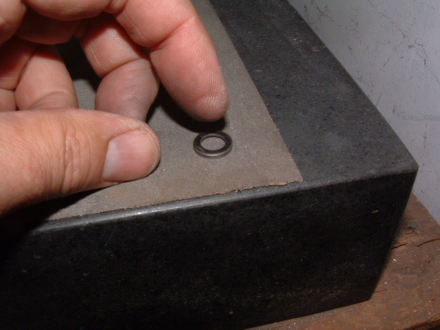
Here is HOW you thin down the stock Zenoah washers ... 180 grit emery paper or wet/dry on a surface place or piece of glass. Thinning is ONLY done to the side with the counter bore. You work the washer round and round checking it often for equal thickness edge to edge. Stock Zenoah washer thickness is @ .073" give or take. You WANT them taken to @ .067" each. (Pending on piston boss measurement?) Aim for an assembled width of @ .008" to .012" less than piston boss's measurement. |
Here is the finished washer at .067" thickness |
 |
|
 |
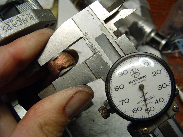
| Here are the MODIFIED washers on the RCMK rod and bearing. * Again the 2 washers are EQUALLY thinned so the assembled width is .008 to .012" less than piston boss's. |
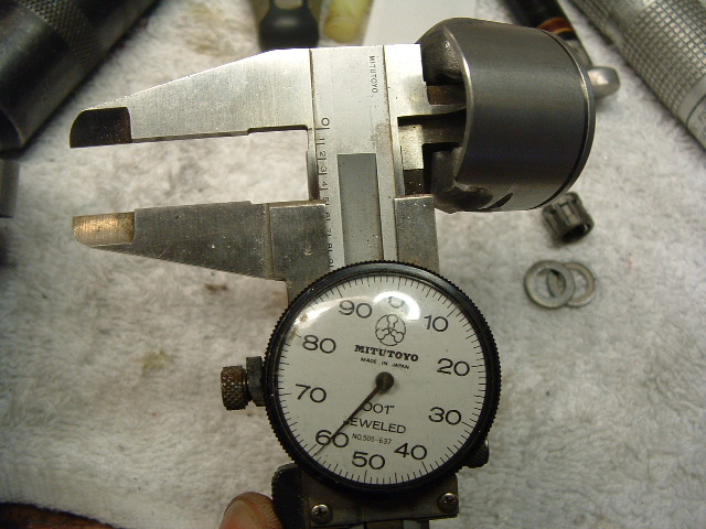
Here is the internal pin boss width within the RCMK piston. * You WANT to have @ .008 to .012" clearance between the bearing/washers and the piston boss's. The actual width is not as important as the assembled clearance and being done with washers of the EXACT same modified width. |
Here the cylinder gasket getting a slight adjustment ,(top right is cut) top left needs to be done yet. |
Final notes:
Unlike the Zenoah "Engine Porting", on the RCMK the divider bridge between the transfer passages is NOT touched, though you can sharpen the edge if you wish.
The modifications shown above are nothing exotic, in doing approximately eight of the S-254 engines so far, the ones done as shown above run the best! These engines seem to do best with more conservative exhaust timing and modest increases in transfer area. You DO NOT need to do wild radical mods to get these engine to run Very Strong!
I do highly recommend doing the basic modifications as shown FIRST, omitting the piston skirt mod... Run it! Then go back in and cut the intake side skirt as shown ... compare the performance.
If you choose to get crazy doing wilder port alteration you will want to have a known baseline, so go after these modifications in steps that will show you what you are gaining or losing along the way.
Regards,
Scott Schneider
MGB Technical Advisor
")

")